Other Pressure Classes
| NPS | DIA D |
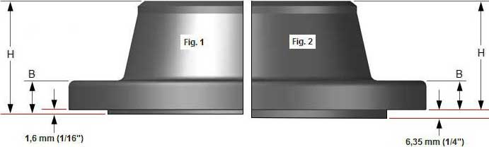
THK B |
DIA A |
DIA OD |
HEIGHT H |
DIA K |
DIA L |
| 1/2 | 3.5 | 0.38 | 1.19 | 0.84 | 1.81 | 2.38 | 5/8 |
| 3/4 | 3.88 | 0.44 | 1.5 | 1.05 | 2 | 2.75 | 5/8 |
| 1 | 4.25 | 0.5 | 1.94 | 1.32 | 2.12 | 3.12 | 5/8 |
| 1¼ | 4.62 | 0.56 | 2.31 | 1.66 | 2.19 | 3.5 | 5/8 |
| 1½ | 5 | 0.62 | 2.56 | 1.9 | 2.38 | 3.88 | 5/8 |
| 2 | 6 | 0.69 | 3.06 | 2.38 | 2.44 | 4.75 | 3/4 |
| 2½ | 7 | 0.81 | 3.56 | 2.88 | 2.69 | 5.5 | 3/4 |
| 3 | 7.5 | 0.88 | 4.25 | 3.5 | 2.69 | 6 | 3/4 |
| 3½ | 8.5 | 0.88 | 4.81 | 4 | 2.75 | 7 | 3/4 |
| 4 | 9 | 0.88 | 5.31 | 4.5 | 2.94 | 7.5 | 3/4 |
| 5 | 10 | 0.88 | 6.44 | 5.56 | 3.44 | 8.5 | 7/8 |
| 6 | 11 | 0.94 | 7.56 | 6.63 | 3.44 | 9.5 | 7/8 |
| 8 | 13.5 | 1.06 | 9.69 | 8.63 | 3.94 | 11.75 | 7/8 |
| 10 | 16 | 1.12 | 12 | 10.75 | 3.94 | 14.25 | 1 |
| 12 | 19 | 1.19 | 14.38 | 12.75 | 4.44 | 17 | 1 |
| 14 | 21 | 1.31 | 15.75 | 14 | 4.94 | 18.75 | 1.1/8 |
| 16 | 23.5 | 1.38 | 18 | 16 | 4.94 | 21.25 | 1.1/8 |
| 18 | 25 | 1.5 | 19.88 | 18 | 5.44 | 22.75 | 1¼ |
| 20 | 27.5 | 1.62 | 22 | 20 | 5.62 | 25 | 1¼ |
| 24 | 32 | 1.81 | 26.12 | 24 | 5.94 | 29.5 | 1.3/8 |
| NPS | NO OF BOLT HOLES |
DIA STUD BOLTS |
LENGTH STUD BOLTS |
| 1/2 | 4 | 1/2 | 2.25 |
| 3/4 | 4 | 1/2 | 2.5 |
| 1 | 4 | 1/2 | 2.5 |
| 1¼ | 4 | 1/2 | 2.75 |
| 1½ | 4 | 1/2 | 2.75 |
| 2 | 4 | 5/8 | 3.25 |
| 2½ | 4 | 5/8 | 3.5 |
| 3 | 4 | 5/8 | 3.5 |
| 3½ | 8 | 5/8 | 3.5 |
| 4 | 8 | 5/8 | 3.5 |
| 5 | 8 | 3/4 | 3.75 |
| 6 | 8 | 3/4 | 4 |
| 8 | 8 | 3/4 | 4.25 |
| 10 | 12 | 7/8 | 4.5 |
| 12 | 12 | 7/8 | 4.75 |
| 14 | 12 | 1 | 5.25 |
| 16 | 16 | 1 | 5.25 |
| 18 | 16 | 1.1/8 | 5.75 |
| 20 | 20 | 1.1/8 | 6.25 |
| 24 | 20 | 1¼ | 6.75 |
Notes:
- Dimensions are in inches unless otherwise indicated.
- The length of the Stud Bolt does not include the height of the chamfers (points).
- ID = Depending on the wall thickness of the pipe, must be specified by the purchaser.