Other Pressure Classes
| NPS | OD | D | B (WNF) |
B (BLF) |
H | A |
| 26 | 661.9 | 785 | 39.8 41.4 |
43 44.6 |
87 88.6 |
684 |
| 28 | 712.7 | 835 | 43 44.6 |
46.2 47.8 |
94 95.6 |
735 |
| 30 | 763.5 | 885 | 43 44.6 |
49.3 50.9 |
98 99.6 |
787 |
| 32 | 814.3 | 940 | 44.6 46.2 |
52.5 54.1 |
106 107.6 |
840 |
| 34 | 865.1 | 1005 | 47.7 49.3 |
55.7 57.3 |
109 110.6 |
892 |
| 36 | 915.9 | 1055 | 50.9 52.5 |
57.3 58.9 |
116 117.6 |
945 |
| 38 | 968.2 | 1125 | 52.5 54.1 |
62 63.6 |
122 123.6 |
997 |
| 40 | 1019 | 1175 | 54.1 55.7 |
65.2 66.8 |
127 128.6 |
1049 |
| 42 | 1069.8 | 1225 | 57.3 58.9 |
66.8 68.4 |
132 133.6 |
1102 |
| 44 | 1120.6 | 1275 | 58.9 60.5 |
70 71.6 |
135 136.6 |
1153 |
| 46 | 1171.4 | 1340 | 60.4 62 |
73.1 74.7 |
143 144.6 |
1205 |
| 48 | 1222.2 | 1390 | 63.6 65.2 |
76.3 77.9 |
148 149.6 |
1257 |
| 50 | 1273 | 1445 | 66.8 68.4 |
79.5 81.1 |
152 153.6 |
1308 |
| 52 | 1323.8 | 1495 | 68.4 70 |
82.7 84.3 |
156 157.6 |
1360 |
| 54 | 1374.6 | 1550 | 70 71.6 |
85.8 87.4 |
160 161.6 |
1413 |
| 56 | 1425.4 | 1600 | 71.6 73.2 |
89 90.6 |
165 166.6 |
1465 |
| 58 | 1476.2 | 1675 | 73.1 74.7 |
91.9 93.5 |
173 174.6 |
1516 |
| 60 | 1527 | 1725 | 74.7 76.3 |
95.4 97 |
178 179.6 |
1570 |
| NPS | G | K | L | No of Bolts |
Stud Bolt Dia x L |
|
| 26 | 711 | 744.5 | 22.2 | 36 | 3/4 | 140 |
| 28 | 762 | 795.3 | 22.2 | 40 | 3/4 | 146 |
| 30 | 813 | 846.1 | 22.2 | 44 | 3/4 | 146 |
| 32 | 864 | 900.1 | 22.2 | 48 | 3/4 | 146 |
| 34 | 921 | 957.3 | 25.4 | 40 | 7/8 | 159 |
| 36 | 972 | 1009.6 | 25.4 | 44 | 7/8 | 165 |
| 38 | 1022 | 1070 | 28.6 | 40 | 1 | 178 |
| 40 | 1080 | 1120.8 | 28.6 | 44 | 1 | 178 |
| 42 | 1130 | 1171.6 | 28.6 | 48 | 1 | 184 |
| 44 | 1181 | 1222.4 | 28.6 | 52 | 1 | 190 |
| 46 | 1235 | 1284.3 | 31.8 | 40 | 1.1/8 | 203 |
| 48 | 1289 | 1335.1 | 31.8 | 44 | 1.1/8 | 203 |
| 50 | 1340 | 1385.9 | 31.8 | 48 | 1.1/8 | 210 |
| 52 | 1391 | 1436.7 | 31.8 | 52 | 1.1/8 | 216 |
| 54 | 1441 | 1492.2 | 31.8 | 56 | 1.1/8 | 216 |
| 56 | 1492 | 1543 | 31.8 | 60 | 1.1/8 | 222 |
| 58 | 1543 | 1611.3 | 34.9 | 48 | 1¼ | 229 |
| 60 | 1600 | 1662.1 | 34.9 | 52 | 1¼ | 235 |
Indications:
- OD = Diameter at Weld Bevel
- D = Overall Diameter of Flange
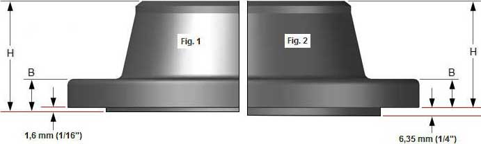
- B (WNF) = Minimum Thickness of Welding Neck Flange
- B (BLF) = Minimum Thickness of Blind Flange
- H = Length thru Hub
- A = Diameter at Base of Hub
- G = Outside Diameter of Raised Face
- K = Bolt Circle Diameter
- L = Diameter of Bolt Holes
General notes:
- Dimensions are in millimeters unless otherwise indicated.
- For dimensions "B" and "H" click IMPORTANT.
- Blind flanges ASME B16.47 series A flanges (≥ NPS 26) are MSS SP-44 flanges.
ASME has incorporated the MSS-SP44 specification into B16.47 Series A and the API 605 Specification into B16.47 series B.
These specification include only Welding Neck and Blind Flanges. - Dimensions for Classes 400, 600 and 900 NPS 38 and larger for Series B flanges are the same as for the Series A flanges.
- The length of the Stud Bolt does not include the height of the chamfers (points).